Flow Quik
What It Is


FAST!
Flow testing is fast with Flow Quik. Stop wasting time adjusting depression, reading manometers, and punching calculator buttons to compute the CFM. Flow Quik users actually report testing ten times faster than with a traditional flow bench.
Affordable!
Traditional flow benches typically cost $2500 to $12000, or more. The high cost has kept many from the benefits of flow testing. Flow Quik breaks through the cost barrier. You can purchase a Flow Quik measuring unit with Flow Quik software for less then a third the price of the cheapest flow bench! The measuring unit is just $779 and the software is only $99.
Easy to Use!
Flow Quik shows CFM directly on a large easy-to-read digital display. You do not need a calculator and a degree in higher mathematics to convert manometer readings into CFM. Just connect your head, open the valve, turn on the vacuum and read CFM directly on the large digital display.
Air Speed Too!
The latest version of Flow Quik supports the use of hand-held pitot tubes” to directly measure the air speed in the port. A single switch selects readout in air speed or pressure. Pressure readout is handy for checking carburetor jet signals.
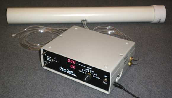
How it Works

Flow Quik works with a vacuum source that you supply. This can be your shop vacuum or a more powerful source. (See Flow Quik Tips & Advice for hints on vacuum sources.) It does not control the amount of vacuum (commonly called “depression”). Instead, it measures the depression and the flow, and then adjusts the displayed flow to what it would be at the standard depression. You select the standard depression by the range knob on the front panel. The method Flow Quik uses to adjust flow to standard conditions is a well established principle of fluid dynamics that is commonly used in flow bench work.
Flow Quik uses an averaging velocity tube to measure flow. The velocity tube and the orifice (commonly used in flow benches) are both members of a broader classification of flow measuring devices called differential producers. With both of these, the flowing air produces a pressure drop that is proportional to the square of the flow. The combination of this nonlinear response and high pressure drops gives the orifice a limited range. This is why flow benches need several orifices of different sizes.
Flow Quik’s averaging velocity tube is a low restriction device, giving it a low pressure loss. Therefore, it can measure a broader range of flows than an orifice. It’s range can be further extended by testing at less than standard depression and allowing Flow Quik to compensate the flow to what it would be at standard depression.
Flow Quik FAQ

The idea for Flow Quik originated from a suggestion made by David Vizzard combined with a request from one of our international dealers for an affordable alternative to standard flowbenches. David has evaluated Flow Quik and written about it favorably in his books and articles.
Flow Quik was originally intended to be used as a supplement to a flow bench, or as a learning tool for beginning head porter who could not yet afford a flow bench. Still many owners are successfully using Flow Quik as their only flow bench.
There are differences: Flow Quik is faster, easier, and more productive. On the other hand, Flow Quik does not control the depression. Depending upon the capacity of your air mover, it may not use as high a depression as a flow bench, especially when at high lifts on large heads. The method that Flow Quik uses to adjust flow readings to a standard depression is not valid for all flow conditions, especially when the actual depression is very small.
The maximum ACTUAL CFM of the standard 2 inch Flow Quik is 330. Heads that flow more than this at 28 inches, can still be tested at less than 28 inches and Flow Quik will provide flow values adjusted to 28 inches. Minimum measurable flow is 7 CFM.
top of page
The maximum ACTUAL CFM of the 3 inch Flow Quik is greater than 700 CFM. Minimum measurable flow is 17 CFM. If your air mover is too weak to supply what your head flows, you will be better off using the 2 inch model. The 3 inch Flow Quik does not include the flex hose that comes with the 2 inch model.
A combo unit is also available that combines both 2 inch and 3 inch flow tubes with one set of electronics.
| Head | CFM | Flow Quik Model |
| 23º Small Block Chevy | Below 330 | 2 inch |
| Other Small Block Chevy | 330-400 | 3 inch |
| Big Block Chevy | 360-400 | 3 inch |
| Prostock Big Block Chevy | 540 | 3 inch |
| Valve Size | CFM | Flow Quik Model |
| Below 2.1 inch | Below 330 | 2 inch |
| Above 2.1 inch | 330-400 | 3 inch |
Some Flow Quik users connected two vacuums together with a Y fitting to get higher depressions. They report that the corrected CFM numbers did not change, but at high flow levels the numbers were more stable. Many users have built their own air supply. You can purchase a set of blueprints with illustrated instructions for building an air supply and test plenum.
The size of the vacuum does not affect the value of the corrected flow numbers. At high flow levels the numbers will be more stable with a stronger vacuum.
Flow Quik has a second digital display for showing depression. It also shows air speed for pitot tube air velocity probes and booster signal for carburetor tests.
Flow Quik software uses the same data file format as Flow Pro. Flow Quik data files can be used directly by Dynomation. Other programs may be able to read Flow Quik reports saved in an ASCII file format.
Connect the carburetor booster signal to the “S” tap on the front panel and switch the bottom display to show pressure. The software has special modes for carburetor testing and data display.
200MHz Pentium with Windows. A USB port is required for connecting the Flow Quik measuring unit.
Shop vacuum or other air supply. The size of the head dictates the air supply capacity. Heads can be tested with a weak air source, but results are better with a stronger source. See Flow Quik Tips & Advice for help on building an air supply. You can purchase a set of blueprints with illustrated instructions for building an air supply and test plenum.
An adapter for connecting to the head which shrouds the valve in the same way that the cylinder walls do. Most Flow Quik owners are using standard flow bench style adapters.
A test plenum. This is a box on which to set the adapter. The box also provides a good place to put the depression pickup. The standard flowbench hole for mounting flowbench style adapters is a 5 inch diameter hole with a square 4 hole bolt pattern around it. The bolt pattern is 5 inches on a side. The hose from Flow Quik to the box should enter the box on the bottom directly beneath the 5 inch hole. Connecting the hose to the side of the box can produce an uneven pressure distribution at the 5 inch hole.
A pair of special weak valve springs.
A mechanism to open the valve and measure the opening.
Radiused inlet guide for intake ports (necessary).
Stub pipe for exhaust ports (optional but recommended for best results).
Pitot tubes for measuring air speed in the ports (only needed if checking air speeds).
Tips & Advice Test

Repeatable valve opening is a must for flow testing. Over the years various valve opening fixtures have been designed. You can buy fixtures or fabricate your own. Most valve opening fixtures use one of three different methods.
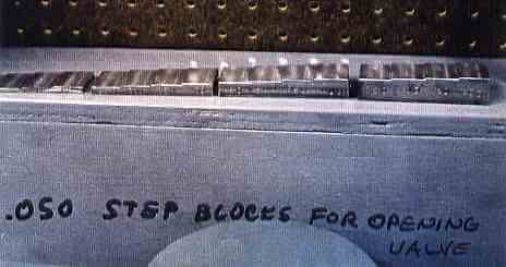 The first method uses a dial indicator to measure the valve lift. Usually a screw pushes the end of the valve stem and the indicator measures the movement of the screw. The second method also uses a 1/4-20 screw to open the valve. A 20 tpi thread pitch produces .050 inch of lift for each full turn. With this method it is important to be able to accurately turn the screw EXACTLY a full turn.
The third method also uses a screw, but the screw does not open the valve. Instead it is turned until it just contacts the end of the valve. The valve is then opened by inserting spacers between the screw and the valve.
Head adapters attach to the block surface of the head. They provide repeatable shrouding of the valves. Air is blown (for exhaust ports) or pulled (for intake ports) through the head adapter. Traditional flow benches have a work surface with a large hole on which a head adapter mounts. The head is then mounted on the top of the adapter. This type of head adapter can be used with Flow Quik by building a box with a large hole in the top on which you mount the adapter. We have named this box a “Test Plenum”. The box should rest on legs so that you can bring the hose from the Flow Quick measuring unit into the bottom of the box directly below the hole in the top of the box. Do not bring the hose into the side of the box as this can result in uneven depression across the large hole. See the advice below on designing vacuum sources for recommendations regarding the sturdiness of the box.
Flow Quik automatically compensates for variations in depression. “Depression” is the flow bench name for test vacuum (on intake tests) or pressure (on exhaust tests). As with any compensation it is better get the depression close to the standard value (usually 28 inches). Some heads (small block Chevy, for example) suffer from flow problems that do not appear until the air speed in the port passes a critical value. The only way to achieve the required air speed for properly test these ports, is to provide adequate depression at the higher lifts. When testing these kinds of heads your vacuum source should be able to provide about 28 inches at all lifts. This is beyond the capability of a single shop vacuum for the small block Chevy and similar size heads.
Two vacuums can be joined together with a Y fitting to produce a stronger vacuum source. Many Flow Quik users have also built their own vacuum source. Usually these boxes do not have the filters that a shop vacuum has. If you do this you should take extra care to clean intake ports before testing so that debris is not drawn into the motors.
Vacuum motors are readily available from Grainger , Hesco , and other supply houses. We recommend building a box to hold more motors than you plan to use. Screw a plywood cover over the ununsed motor mounting holes. This makes it easy to install more motors, if you find that you need more vacuum. The box should have two chambers with the motors mounted in the wall that divides the chambers. The motors will pull air from one chamber (creating a vacuum for testing intake ports), and push it into the other chamber (creating a pressure for testing exhaust ports).
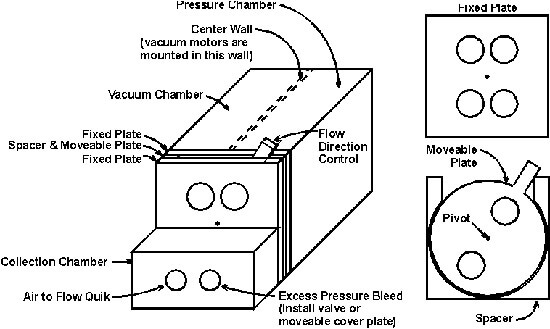
The diagram shows an air supply with a flow direction control. The excess pressure bleed is needed to prevent over-ranging Flow Quik’s depression sensor at low lifts. If it is constructed so as to provide fine control of the opening it can be used as a depression adjustment.
We sell a set of blueprints and fully illustrated instructions for building an air supply and a test plenum. The instructions include 50 color photos, a materials list, a sources list, and a cutting diagram. These are well worth purchasing since they will pay for themselves when they save from you one or two mistakes.
The fixed plates can be made from 3/4 inch thick melamine coated particle board. This material is used to make cheap shelves. It is available in various widths and 4 x 8 foot sheets at building supply stores. A good material for the moveable plate and spacer is 1/4 thick PVC sheet. Place a sheet of paper between the spacer and one of the fixed plates so that the moveable plate will have clearance to operate. A 1/4 inch dia. dowel pin makes a nice pivot. The rest of the unit can be constructed from the melamine board or 3/4 inch plywood. Reasonable sizes for the fixed plate are 18 x 18 inches with 4 inch holes.
When planning your installation consider which direction the air will blow when it exits the unit into the room. It’s no fun chasing papers around the room after the air supply blows them off your workbench.
Keep in mind that 28 inches of water is approximately 1 psi. At 28 inches of depression a one square foot panel will have a force of 146 pounds on it. Therefore your box must be very sturdy. 3/4 inch plywood works well.
The work surface on a standard flow bench has a 5 inch dia. hole in the center of a 4 bolt pattern. The standard thread size for the 4 bolts is 1/4 – 20, but some manufacturers now use 5/16.
| 1st Choice | 2nd Choice | 3rd Choice | 4th Choice |
| Grainger Part No. 4M903 Hesco Part No. L-115923 Ametek Part No. 115923 120 VAC, 10.8 Max Amps 100 CFM at 28 inches 122 CFM thru 2 inch orifice 100.4 inch H2O in sealed chamber Overall height: 6.2 inch Diameter: 5.7 inch | Grainger Part No. 2M424 Hesco Part No. L-116670-50 Ametek Part No. 116670-50 240 VAC, 4.0 Max Amps 80 CFM at 28 inches 102 CFM thru 2 inch orifice 87.8 inch H2O in sealed chamber Overall height: 5.6 inch Diameter: 5.7 inch | Grainger Part No. 2M421 Hesco Part No. L-116669-50 Ametek Part No. 116669-50 120 VAC, 7.7 Max Amps 70 CFM at 28 inches 94 CFM thru 2 inch orifice 90.2 inch H2O in sealed chamber Diameter: 5.7 inches Overall height: 5.6 inches | Grainger Part No. 2M194 Hesco Part No. L-116309-00 Ametek Part No. 116309-00 120 VAC, 6.8 Max Amps 57 CFM at 28 inches 112 CFM thru 2 inch orifice 63 inch H2O in sealed chamber Diameter: 5.7 inches Overall height: 4.5 inches |
Air Supply Plans

Air Supply Plans
We now offer a set of detailed plans and fully illustrated instructions for building a Flow Quik air supply and a Flow Quik test plenum. The step by step instructions feature:
- 50 full color illustrations
- Blueprints
- Parts list
- Illustrated instructions
- Cutting diagrams
The plans are fully tested and include a parts list with suggested sources.
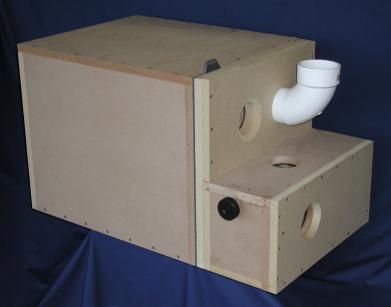
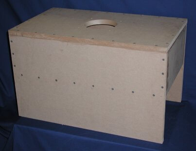
This Air Supply (above) and Test Plenum (below) were built using the Test Plenum and Air Supply plans. To better show the construction, we did not paint them or laminate them.
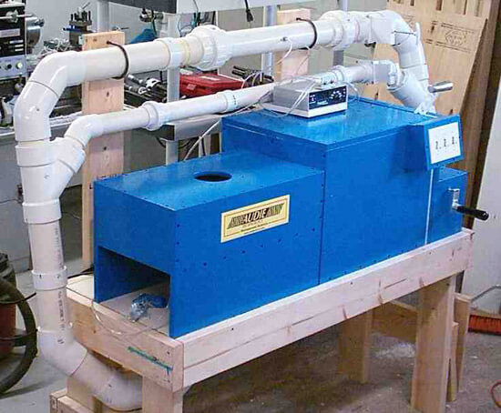
The photo below is Test Plenum and Air Supply built by Farrel Vaughan with his 2 & 3 combo Flow Quik. Notice the gate valves at the right end of the 2 inch and 3 inch runs. They are used to shut off the run that is not being used.
Photos

Test stand constructed by Jack Schwendener at Jackson Head Works.
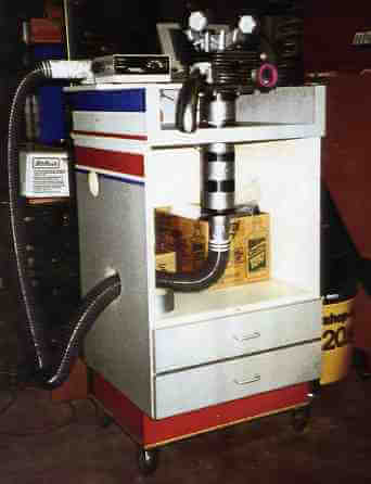 Jack Schwendener of Jackson Head Works in Citrus Heights, CA says, “The overall photos show the Flow Quik unit installed on a stand that one of my customers gave to me. It was formerly a point-of-sale computer stand in a retail store. I made a few easy modifications to it. I have used standard PVC pipe fittings in suitable sizes for the dummy “cylinder” and connecting piping. The head adaptor was made using 1 inch thick clear acrylic. I used a head gasket to lay out the dimensions, including the head dowels, which are short sections of suitable size rubber hose. The acrylic plate was bored (with a standard adjustable boring head) to fit the PVC pipe in a benchtop “mill/drill”. The PVC cylinder was then epoxied in place. The PVC pipe fittings are joined with duct tape so it can be setup and taken down easily. When using PVC fittings, it is sometimes necessary to remove flashing, strengthening ribs, etc. as required.
“As you see from photos, I like to test the entire flow path so I have installed a manifold on the intake side (with an entrance bell made from modeling clay) and a mandrel-bent exhaust header stub.
A Very Attractive Flow Quik Bench.

Air Cooled Engines Plus
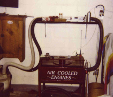
John Aller at Air Cooled Engines Plus found that at higher flow levels the corrected flow numbers are more stable with a stronger vacuum. He hooked two shop vacs together with a Y fitting to get a higher depression. He reported that the corrected CFM numbers did not change, but at higher flow levels the numbers were more stable.
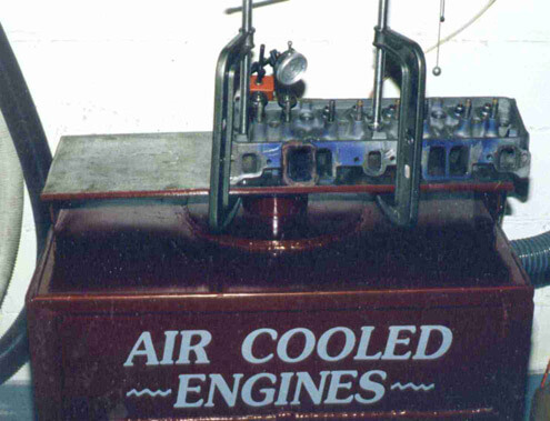
Flow Quick in Use
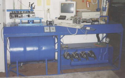
McMaster Rebuilds bench using tangental discharge vacuum motors.
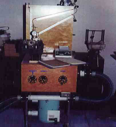
Jim Lepetich built this bench for his Flow Quik
Flow Quik In Use
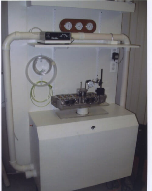
Dave’s Service Center Flow Quick
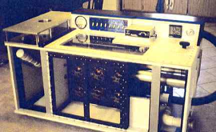
Mark Glendening’s Flow Quick Bench
Flow Quick in Use
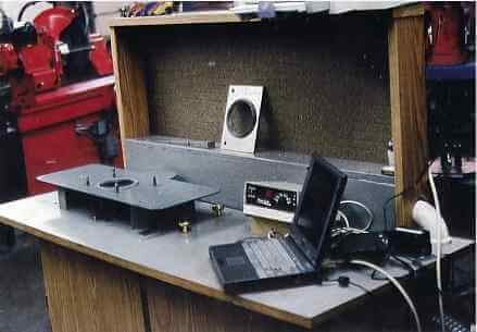
Mike Tiry’s Creation
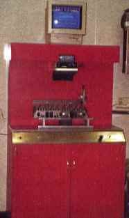
Flow Quik built into a bench at Empson Automotive
Two Views of John Worth’s Bench
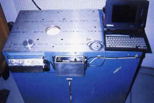
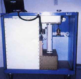
Flow Quik Combo Model with Test Plenum & Air Supply
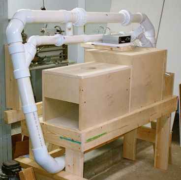
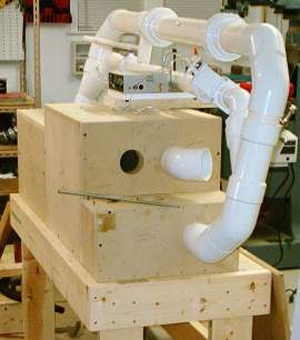

Test Plenum and Air Supply built by Farrel Vaughan with his 2 & 3 combo Flow Quik. Notice the gate valves at the right end of the 2 inch and 3 inch runs. They are used to shut off the run that is not being used.
Testimonials
What Expert Racers and Engine Builders say about Flow Quick.
John Parker-Vintage Performance Development Engine Builder and Racer
After one week with the Flow Quik I took 4 seconds off my time at Watkins Glen and was beating Camaros and Mustangs in my Volvo.
John Holm-AutoTech Consulting Head Porter, Engine Builder and Consultant
I rank the Flow Quik as a superb piece of equipment, and for the price I can not believe every grass roots racer does not already have one. I feel the results are very legitimate and I will continue to use mine for the majority of my work. I love the speed at which I can now flow heads. I can do it in my basement and have a head done in 15 minutes. If I have to use the bigger bench it takes me about 1 hour to set up and test 1 port. Not having to set the depression is a time saving feature. I know that some of the new high dollar flow benches have a feature that automatically sets the depression with each valve lift. Those machines cost thousands of dollars more than the Flow Quik. For the grass roots racer, or the shop that needs a cost effective way to flow cylinder heads the Flow Quik is extremely hard to beat.
John Schwender-Jackson Head Works Head Porter
I hooked up my old (386SX) laptop to the FQ, using the software you provided and the shopvac you recommended. Everything went smooth, the unit seems very quick and easy to operate. After using some homemade units of manometers it was so easy it was almost scary. Having the live data displayed on the screen is great. I like having the depression which is displayed on the monitor because I like to stay over 6 inches. Although, I prefer this method, the Flow Quik unit alone also works well.
Jack Kane-E.P.I. Inc. Engineer
Flow Quik was easy to use, repeatable and compact. For a low budget racer trying to learn more about flow, this unit is the perfect choice.
Bruce McMaster- McMaster Rebuilds Head Porter and Engineer Builder
I purchased a Flow Quik and I have incorporated your measuring system into a homemade bench. I have used a 55 gallon drum as a depression surge absorber and I am using four 125 CFM blowers as the vacuum source. I have been experimenting with just one take runner and just one exhaust runner on a head and have been getting repeatability of 0.25 of one percent. I find that care must be taken that valve opening is set exactly (I have the Brzezinski opening system). I am very happy with your product.
Flow Bench Companies
Jamison Equipment
1908 11th St.
Emmetsburg, IA 50536
Phone: (800) 841-5405
Fax: (712) 852-3570
jamisone@ncn.net
www.jamisonequipment.com/
Saenz
Contact: Mr. Saenz
Pedro Zanni 1599
7600 Mar Del Plata
Argentina
Phone: +54-223-479-2913
Spanish only
Fax: +54-223-465-0100
English okay
saenz@saenzdynos.com.ar
English okay for E-mail
Equipment & Books
Sources for Flowbench Equipment
Brezezinski Racing Products
N 50 W 23001 Betker Drive
Pewaukee, WI 53072
Phone: (262) 246-8577
Fax: (267) 246-7371
www.castheads.com
Motor International
P.O. Box 1
Osceloa, WI 54020
Phone: 1-800-826-6600
Book Recommendations
- Engine Airflow by Harold Bettes
- How To Build & Modify Chevrolet Small-Block V-8, Camshafts & Valve trains
- Flathead Fever by Mike Davidson
- Flow Numbers – self-published by Trey
- Musgrove, 1526 Willowview Dr., Grove City, OH 43123, (614) 875-1401
- Harley-Davidson Evolution 1340 Performance Tests by Jerry Branch, Branch Flowmetrics, (714) 827-1463
- How to Build, Modify, & Power Tune Cylinder Heads by Peter Burgess & David Gollan
- How to Build & Modify Chevrolet Small Block V-8 Cylinder Heads by David Vizard
- Porting Notebook self-published by Bill Jones, 3294 Meadow Wood Way,Salt Lake City, UT 84118, (801) 969-3807
- The Chevrolet Power Manual available from Chevy dealers
- The Chevrolet Racing Engine by Bill Jenkins
- The Design and Tuning of Competition Engines by Philip H. Smith
- The Scientific Design of Exhaust & Intake Systems by Philip H. Smith and John C. Morrison
